Abstract: In view of fact that current upgrading of small household electrical appliances is getting faster and faster, especially in Ningbo, there are many small household electrical appliance enterprises, homogenization is serious, and price war is getting worse. All companies require R&D personnel to compress product design cycles and improve product qualification rates from moldflow for coffee maker mold.
Moldflow software used to simulate injection molding process of plastic parts. Various useful parameters are obtained before test, problems are found in advance and improved, which greatly shortens mold production cycle. In this paper, analysis of gate, filling, packing, warping of plastic parts, find out cause of warpage deformation of product, and propose improvement suggestions: change gate position to ensure uniform melt filling; Heat treatment performed to reduce warpage.
Coffee maker mold: Preface
At present, with improvement of people’s living standards, higher and richer requirements put forward for various products. As a characteristic industry in Ningbo, small household appliance industry cluster is also facing higher challenges. If you want to stand on market, you must have a higher level of research and development, faster mold manufacturing, and better after-sales service. Most of small home appliance mold are plastic parts, so production cycle of products depends on production cycle of plastic molds. In this paper, coffee maker mold, using more mature CAD/CAM software on market – mold flow analysis software Moldflow, analyzes filling, gate, cooling and warpage of mold, and gain more valuable time for mold improvement design.
Plastic parts process of coffee maker mold analysis
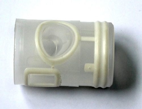
Figure 1(a) is a three-dimensional view of coffee maker mold, and Figure 1(b) is a two-dimensional view. Size of plastic part is larger 360×270×170,
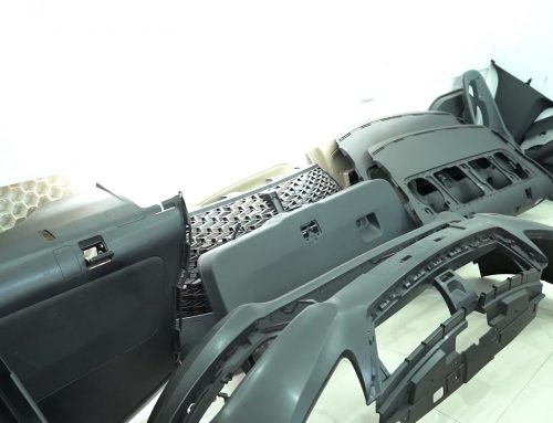
Wall is thin, structure is complicated, inside has inverted buckle, slender cylinder (screw hole), upper and lower asymmetry, left and right asymmetry, etc., which bring many uncertain factors to filling pressure and other links. Inner and outer surfaces of plastic parts are not smooth, difficulty in manufacturing and forming mold is also increased to some extent. Plastic material uses ABS (acrylonitrile-butadiene-styrene copolymer), which has high melt viscosity, is sensitive to temperature and shear rate, and requires higher mold manufacturing. Therefore, in order to improve success rate of test mode, it is particularly important to perform mold flow analysis on design process of plastic part before mold processing.
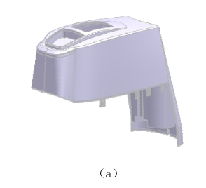
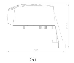
Figure 1 coffee machine mold
Moldflow analysis: caffe maker mold
1 Pre-processing of finite element model
Use UG software to complete 3D model of plastic part, export it to x_t format, and then import this file through AMDL which comes with CAD DOCTOR, do some simplification and repair processing in CAD DOCTOR software, such as removing duplicate faces, free edges, short lines, broken Surface, etc., to simplify small structures that do not affect analysis, such as steps within 1mm, rounded corners below 1mm. After mold manufacturing, import it into Moldflow for meshing. Double-layer mesh used. Maximum aspect ratio of triangle is required to be controlled below 13, average aspect ratio is controlled below 10, free edge, multiple edges are 0, misaligned face must be 0, intersecting unit and full overlap unit are 0, matching percentage is controlled at around 90%, and model fully meets required requirements.
Figure 2 shows grid statistics.
Figure 2 Grid statistics
2 analysis of gate location
Choice of gate location plays a crucial role in mold design. It directly affects shape and speed of flow of molten plastic front, which will affect warpage of plastic part and have a very obvious influence on weld line and also plays a decisive role in holding pressure. In particular, multi-gate injection should consider position of gate, control flow mode of melt filling, and avoid over-pressure. This mold uses two gates to feed glue. Due to particularity of plastic parts, glue not balanced. Figure 3 is a diagram of end filling path, from which it can be seen that filling time at each of the most distal ends of model is inconsistent to coffee maker mold.
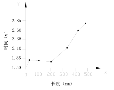
Figure 3 Filling path graph
3 analysis of the runner system
Mold is one out of one, and runner system is relatively simple. However, it is also necessary to ensure that plastic parts can be filled smoothly, flow rate and gate rate are guaranteed to be below maximum shear rate of material. In order to save costs, flow size design is as small as possible. Therefore main channel has a hole diameter of 4 mm and a taper angle of 1 °. Shunt channel made large (12 mm) and small (8 mm). In order to reduce filling and holding pressure, shear rate reduced, gate width is 6 mm, and thickness is 2. 5 mm. Measured shear rate is up to 26897 S-1, which meets maximum shear rate of 50000 S-1, as shown in Figure 4.
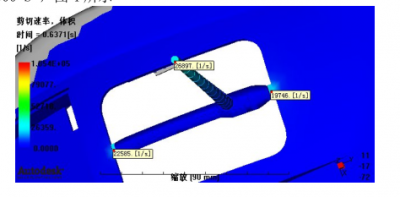
Figure 4 Shear rate
4 Filling analysis
Filling analysis is very important in entire simulation analysis. It simulates filling entire plastic part. It can find many problems before test, and can be corrected in time.
Figure 5 is a flow front temperature map. It can seen from figure that it is basically consistent, which indicates that filling process is not obstructed and process is smooth by moldflow.
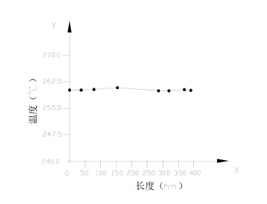
Figure 5 Front temperature path graph
Figure 6 is a surface shear stress diagram, maximum value is 0. 1167MPa, yield limit of material is 0. 3MPa, according to first strength theory, it known that condition satisfied and safe.
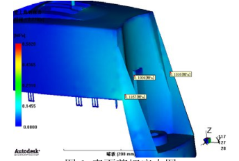
Figure 6 Surface shear stress
5 Packing pressure – warping analysis
Figure 7 shows time-pressure diagram at injection site, showing pressure at injection site from end of hold. It found that peak value of injection pressure higher than pressure value at the time of injection/pressure holding switching. This indicates that there a partial loss of pressure during mold manufacturing process, it found that one end of filling squeezed and a part of pressure consumed.
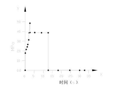
Figure 7 Time—Pressure graph
Figure 8 is pressure path diagram when injection/pressure holding switch is performed. Pressure difference is about 25 MPa at most. Reason is mainly due to shape of plastic part and limitation of glue inlet. Molding time of end of part cannot be consistent, squeezing effect occurs, resulting in a large difference in pressure between squeeze zone and non-backlog zone. Therefore, internal stress is abnormally high, and warpage problem occurs when it cooled. Fig. 9 shows result of warpage analysis, and maximum warpage deformation reaches 1. 3 mm.
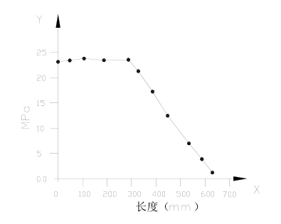
Figure 8 Stress path graph
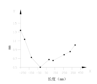
Figure 9 warp path graph
Conclusion
Paper studied injection defects of coffee machine cap. Plastic melt filling imbalance caused by plastic injection molding causes internal stress of two parts to be excessively large and warpage. Problems such as excessive stress and warpage. Suggestions for improvement: Change position of gate to ensure uniform filling of melt as much as possible; After mold removed, parts subjected to stress removal treatment to reduce warpage.
Apply CAD/CAE software to comprehensively consider product design, mold design and mold-testing process before processing. It greatly reduce time delay caused by unreasonable design, increase design credibility, avoid design defects, and shorten development cycle. Purpose gradually applied in small household appliance enterprises. However, there are certain misunderstandings and shortcomings in the research and understanding of certain parameters. Further research and exploration need for many process related aspects to caffe maker mold.